What happened?
A printer displaying the message "Preheat error bed" encountered an error while heating up the heatbed. If the heatbed temperature does not increase more than 2 ºC for 240 seconds, the printer starts a safety feature, which instantly kills the heating process and displays the message on the screen. The printer then waits for the user to inspect all parts and if needed fix the issue.
Error name: Preheat error bed
Error code: #12201
How to fix it?
The inability to heat up the heatbed might indicate some issue with the wiring, either the heater or the thermistor cables are possibly damaged.
A visual inspection
Before breaking out the multimeter you should check the heatbed, where the thermistor and heater resides, that no wires have broken off the sensor or heater themselves. While the printer is turned off, carefully try to move the wires by hand. If any of them have come detached your search is over and the part needs to be changed. It is not recommended to solder these wires, moreover, for the thermistor, it will change it's resistance and thus readings. Spare parts can be found in our e-shop, or you can contact Customer support for assistance.
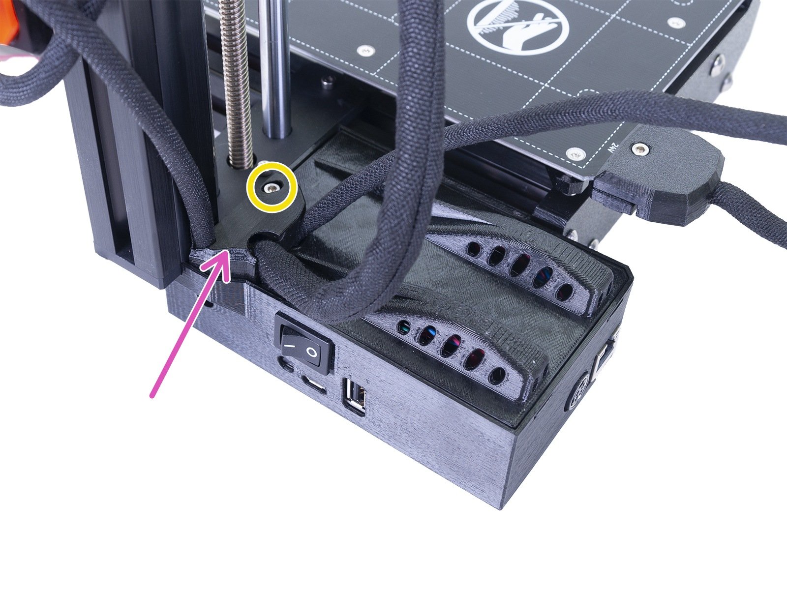
Also, make sure everything is connected to the Buddy mainboard, inside its case. Loosen the one screw securing the cover (circled in the picture below), remove the top cable cover and flip it open to reveal the board.
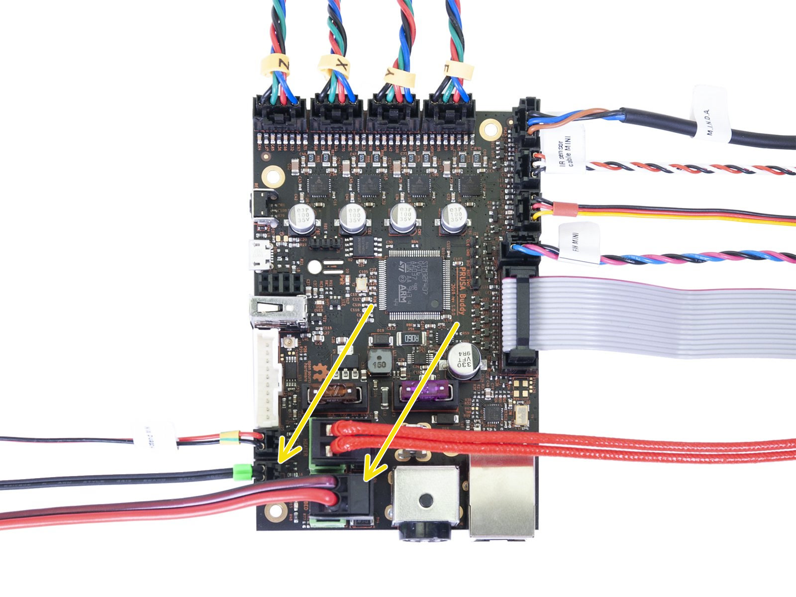
Check that all the connectors are secure in their sockets, according to the picture below. Focus on the thermistor and heater cables (yellow arrows). Though unlikely, rough shipping or handling could have shaken the heater or thermistor cables loose.
Checking the resistance
The table below describes the correct resistance for each part, as well as what scale you should set your meter to. We have another more in-depth guide on Multimeter usage. All thermistors are rated to be 100 kΩ at 25 °C. To be realistic, with a varying temperature between 20 °C and 30 °C, you can expect a wider range of readings (~85-105 kΩ), than with the heater.
Part |
Resistance |
Multimeter scale |
|
Thermistors (Bed and hotend) |
[80 kΩ - 125 kΩ] |
200 kΩ |
|
Heatbed |
[4.5 Ω - 6.5 Ω ] |
200 Ω |
Where to measure
For every component, there are several options, our main focus will be on the connectors. The measurement appears on the multimeter LCD as soon as the measurement probes touch the component. To obtain the correct and relevant values, this is where you need to apply the probes:
- Thermistors: metal inserts in plastic connectors

- Heater cables: screws holding the cables in the connector

Parts replacement guide(s)
In case you find some parts are faulty, please order them using our e-shop, then follow the service guide(s):
2 comments